手机版
手机版

|
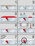
Introduction to Nondestructive Testing For visitors who are not already familiar with NDT, the general information below is intended to provide a basic description of NDT and the most common test methods and techniques used when performing NDT. As such it is not highly detailed or all encompassing, and for more comprehensive information readers should refer to ASNT publications such as the ASNT NDT Handbooks or the ASNT Personnel Training Publications (PTP) Classroom Training Series, all of which are available from ASNT’s bookstore. Also, standards covering these test methods are listed on the "Codes and Standards Bodies" page under the NDT Resources Center tab. To maintain consistency, the techniques described for each test method are those listed in the 2011 edition of ASNT’s Recommended Practice No. SNT-TC-1A. What Is Nondestructive Testing? Nondestructive testing (NDT) is the process of inspecting, testing, or evaluating materials, components or assemblies for discontinuities, or differences in characteristics without destroying the serviceability of the part or system. In other words, when the inspection or test is completed the part can still be used. In contrast to NDT, other tests are destructive in nature and are therefore done on a limited number of samples ("lot sampling"), rather than on the materials, components or assemblies actually being put into service. These destructive tests are often used to determine the physical properties of materials such as impact resistance, ductility, yield and ultimate tensile strength, fracture toughness and fatigue strength, but discontinuities and differences in material characteristics are more effectively found by NDT. Today modern nondestructive tests are used in manufacturing, fabrication and in-service inspections to ensure product integrity and reliability, to control manufacturing processes, lower production costs and to maintain a uniform quality level. During construction, NDT is used to ensure the quality of materials and joining processes during the fabrication and erection phases, and in-service NDT inspections are used to ensure that the products in use continue to have the integrity necessary to ensure their usefulness and the safety of the public. It should be noted that while the medical field uses many of the same processes, the term "nondestructive testing" is generally not used to describe medical applications. NDT Test Methods Test method names often refer to the type of penetrating medium or the equipment used to perform that test. Current NDT methods are: Acoustic Emission Testing (AE), Electromagnetic Testing (ET), Laser Testing Methods (LM), Leak Testing (LT), Magnetic Flux Leakage (MFL), Liquid Penetrant Testing (PT), Magnetic Particle Testing (MT), Neutron Radiographic Testing (NR), Radiographic Testing (RT), Thermal/Infrared Testing (IR), Ultrasonic Testing (UT), Vibration Analysis (VA) and Visual Testing (VT). The six most frequently used test methods are MT, PT, RT, UT, ET and VT. Each of these test methods will be described here, followed by the other, less often used test methods. Magnetic Particle Testing (MT) Magnetic Particle Testing uses one or more magnetic fields to locate surface and near-surface discontinuities in ferromagnetic materials. The magnetic field can be applied with a permanent magnet or an electromagnet. When using an electromagnet, 超声波探伤仪http://www.chaoshengbotanshangyi.org the field is present only when the current is being applied. When the magnetic field encounters a discontinuity transverse to the direction of the magnetic field, the flux lines produce a magnetic flux leakage field of their own as shown in Figure 1. Because magnetic flux lines don't travel well in air, when very fine colored ferromagnetic particles ("magnetic particles") are applied to the surface of the part the particles will be drawn into the discontinuity, reducing the air gap and producing a visible indication on the surface of the part. The magnetic particles may be a dry powder or suspended in a liquid solution, and they may be colored with a visible dye or a fluorescent dye that fluoresces under an ultraviolet ("black") light. MT Techniques Yokes Most field inspections are performed using a Yoke, as shown at the right. As shown in Figure 2(a), an electric coil is wrapped around a central core, and when the current is applied, a magnetic field is generated that extends from the core down through the articulated legs into the part. This is known as longitudinal magnetization because the magnetic flux lines run from one leg to the other. When the legs are placed on a ferromagnetic part and the yoke is energized, a magnetic field is introduced into the part as shown in (b). Because the flux lines do run from one leg to the other, discontinuities oriented perpendicular to a line drawn between the legs can be found. To ensure no indications are missed, the yoke is used once in the position shown then used again with the yoke turned 90o so no indications are missed. Because all of the electric current is contained in the yoke and only the magnetic field penetrates the part, this type of application is known as indirect induction. Prods Prod units use direct induction, where the current runs through the part and a circular magnetic field is generated around the legs as shown in Figure 3. Because the magnetic field between the prods is travelling perpendicular to a line drawn between the prods, indications oriented parallel to a line drawn between the prods can be found. As with the yoke, two inspections are done, the second with the prods oriented 90o to the first application. Coils Electric coils are used to generate a longitudinal magnetic field. When energized, the current creates a magnetic field around the wires making up the coil so that the resulting flux lines are oriented through the coil as shown at the right. Because of the longitudinal field, indications in parts placed in a coil are oriented transverse to the longitudinal field. Heads Most horizontal wet bath machines ("bench units") have both a coil and a set of heads through which electric current can be passed, generating a magnetic field. Most use fluorescent magnetic particles in a liquid solution, hence the name "wet bath." A typical bench unit is shown at the right. When testing a part between the heads, the part is placed between the heads, the moveable head is moved up so that the part being tested is held tightly between the heads, the part is wetted down with the bath solution containing the magnetic particles and the current is applied while the particle are flowing over the part. Since the current flow is from head to head and the magnetic field is oriented 90o to the current, indications oriented parallel to a line between the heads will be visible. This type of inspection is commonly called a "head shot." Central Conductor When testing hollow parts such as pipes, tubes and fittings, a conductive circular bar can be placed between the heads with the part suspended on the bar (the "central conductor") as shown in Figure 6. The part is then wetted down with the bath solution and the current is applied, travelling through the central conductor rather than through the part. The ID and OD of the part can then be inspected. As with a head shot, the magnetic field is perpendicular to the current flow, wrapping around the test piece, so indications running axially down the length of the part can be found using this technique. Liquid Penetrant Testing (PT) The basic principle of liquid penetrant testing is that when a very low viscosity (highly fluid) liquid (the penetrant) is applied to the surface of a part, it will penetrate into fissures and voids open to the surface. Once the excess penetrant is removed, the penetrant trapped in those voids will flow back out, creating an indication. Penetrant testing can be performed on magnetic and non-magnetic materials, but does not work well on porous materials. Penetrants may be "visible", meaning they can be seen in ambient light, or fluorescent, requiring the use of a "black" light. The visible dye penetrant process is shown in Figure 7. When performing a PT inspection, it is imperative that the surface being tested is clean and free of any foreign materials or liquids that might block the penetrant from entering voids or fissures open to the surface of the part. After applying the penetrant, it is permitted to sit on the surface for a specified period of time (the "penetrant dwell time"), then the part is carefully cleaned to remove excess penetrant from the surface. When removing the penetrant, the operator must be careful not to remove any penetrant that has flowed into voids. A light coating of developer is then be applied to the surface and given time ("developer dwell time") to allow the penetrant from any voids or fissures to seep up into the developer, creating a visible indication. Following the prescribed developer dwell time, the part is inspected visually, with the aid of a black light for fluorescent penetrants. Most developers are fine-grained, white talcum-like powders that provide a color contrast to the penetrant being used. PT Techniques Solvent Removable penetrants are those penetrants that require a solvent other than water to remove the excess penetrant. These penetrants are usually visible in nature, commonly dyed a bright red color that will contrast well against a white developer. The penetrant is usually sprayed or brushed onto the part, then after the penetrant dwell time has expired, the part is cleaned with a cloth dampened with penetrant cleaner after which the developer is applied. Following the developer dwell time the part is examined to detect any penetrant bleed-out showing through the developer. Water-washable penetrants have an emulsifier included in the penetrant that allows the penetrant to be removed using a water spray. They are most often applied by dipping the part in a penetrant tank, but the penetrant may be applied to large parts by spraying or brushing. Once the part is fully covered with penetrant, the part is placed on a drain board for the penetrant dwell time, then taken to a rinse station where it is washed with a course water spray to remove the excess penetrant. Once the excess penetrant has been removed, the part may be placed in a warm air dryer or in front of a gentle fan until the water has been removed. The part can then be placed in a dry developer tank and coated with developer, or allowed to sit for the remaining dwell time then inspected. Post-emulsifiable penetrants are penetrants that do not have an emulsifier included in its chemical make-up like water-washable penetrants. Post-emulsifiable penetrants are applied in a similar manner, but prior to the water-washing step, emulsifier is applied to the surface for a prescribed period of time (emulsifier dwell) to remove the excess penetrant. When the emulsifier dwell time has elapsed, the part is subjected to the same water wash and developing process used for water-washable penetrants. Emulsifiers can be lipophilic (oil-based) or hydrophilic (water-based). Radiographic Testing (RT) Industrial radiography involves exposing a test object to penetrating radiation so that the radiation passes through the object being inspected and a recording medium placed against the opposite side of that object. For thinner or less dense materials such as aluminum, electrically generated x-radiation (X-rays) are commonly used, and for thicker or denser materials, gamma radiation is generally used. Gamma radiation is given off by decaying radioactive materials, with the two most commonly used sources of gamma radiation being Iridium-192 (Ir-192) and Cobalt-60 (Co-60). IR-192 is generally used for steel up to 2-1/2 - 3 inches, depending on the Curie strength of the source, and Co-60 is usually used for thicker materials due to its greater penetrating ability. The recording media can be industrial x-ray film or one of several types of digital radiation detectors. With both, the radiation passing through the test object exposes the media, causing an end effect of having darker areas where more radiation has passed through the part and lighter areas where less radiation has penetrated. If there is a void or defect in the part, more radiation passes through, causing a darker image on the film or detector, as shown in Figure 8. RT Techniques Film radiography uses a film made up of a thin transparent plastic coated with a fine layer of silver bromide on one or both sides of the plastic. When exposed to radiation these crystals undergo a reaction that allows them, when developed, to convert to black metallic silver. That silver is then "fixed" to the plastic during the developing process, and when dried, becomes a finished radiographic film. To be a usable film, the area of interest (weld area, etc.) on the film must be within a certain density (darkness) range and must show enough contrast and sensitivity so that discontinuities of interest can be seen. These items are a function of the strength of the radiation, the distance of the source from the film and the thickness of the part being inspected. If any of these parameters are not met, another exposure ("shot") must be made for that area of the part. Computed radiography (CR) is a transitional technology between film and direct digital radiography. This technique uses a reusable, flexible, photo-stimulated phosphor (PSP) plate which is loaded into a cassette and is exposed in a manner similar to traditional film radiography. The cassette is then placed in a laser reader where it is scanned and translated into a digital image, which take from one to five minutes. The image can then be uploaded to a computer or other electronic media for interpretation and storage. Computed tomography (CT) uses a computer to reconstruct an image of a cross sectional plane of an object as opposed to a conventional radiograph, as shown in Figure 9. #p#副标题#e#The CT image is developed from multiple views taken at different viewing angles that are reconstructed using a computer. With traditional radiography, the position of internal discontinuities cannot be accurately determined without making exposures from several angles to locate the item by triangulation. With computed tomography, the computer triangulates using every point in the plane as viewed from many different directions. Digital radiography (DR) digitizes the radiation that passes through an object directly into an image that can be displayed on a computer monitor. The three principle technologies used in direct digital imaging are amorphous silicon, charge coupled devices (CCDs), and complementary metal oxide semiconductors (CMOSs). These images are available for viewing and analysis in seconds compared to the time needed to scan in computed radiography images. The increased processing speed is a result of the unique construction of the pixels; an arrangement that also allows a superior resolution than is found in computed radiography and most film applications. Ultrasonic Testing (UT) Ultrasonic testing uses the same principle as is used in naval SONAR and fish finders. Ultra-high frequency sound is introduced into the part being inspected and if the sound hits a material with a different acoustic impedance (density and acoustic velocity), some of the sound will reflect back to the sending unit and can be presented on a visual display. By knowing the speed of the sound through the part (the acoustic velocity) and the time required for the sound to return to the sending unit, the distance to the reflector (the indication with the different acoustic impedance) can be determined. The most common sound frequencies used in UT are between 1.0 and 10.0 MHz, which are too high to be heard and do not travel through air. The lower frequencies have greater penetrating power but less sensitivity (the ability to "see" small indications), while the higher frequencies don't penetrate as deeply but can detect smaller indications. The two most commonly used types of sound waves used in industrial inspections are the compression (longitudinal) wave and the shear (transverse) wave, as shown in Figure 10. Compression waves cause the atoms in a part to vibrate back and forth parallel to the sound direction and shear waves cause the atoms to vibrate perpendicularly (from side to side) to the direction of the sound. Shear waves travel at approximately half the speed of longitudinal waves. Sound is introduced into the part using an ultrasonic transducer ("probe") that converts electrical impulses from the UT machine into sound waves, then converts returning sound back into electric impulses that can be displayed as a visual representation on a digital or LCD screen (on older machines, a CRT screen). If the machine is properly calibrated, the operator can determine the distance from the transducer to the reflector, and in many cases, an experienced operator can determine the type of discontinuity (like slag, porosity or cracks in a weld) that caused the reflector. Because ultrasound will not travel through air (the atoms in air molecules are too far apart to transmit ultrasound), a liquid or gel called "couplant" is used between the face of the transducer and the surface of the part to allow the sound to be transmitted into the part. UT Techniques Straight beam inspection uses longitudinal waves to interrogate the test piece as shown at the right. If the sound hits an internal reflector, the sound from that reflector will reflect to the transducer faster than the sound coming back from the back-wall of the part due to the shorter distance from the transducer. This results in a screen display like that shown at the right in Figure 11. Digital thickness testers use the same process, but the output is shown as a digital numeric readout rather than a screen presentation. Angle beam inspection uses the same type of transducer but it is mounted on an angled wedge (also called a "probe") that is designed to transmit the sound beam into the part at a known angle. The most commonly used inspection angles are 45o, 60o and 70o, with the angle being calculated up from a line drawn through the thickness of the part (not the part surface). A 60o probe is shown in Figure 12. If the frequency and wedge angle is not specified by the governing code or specification, it is up to the operator to select a combination that will adequately inspect the part being tested. In angle beam inspections, the transducer and wedge combination (also referred to as a "probe") is moved back and forth towards the weld so that the sound beam passes through the full volume of the weld. As with straight beam inspections, reflectors aligned more or less perpendicular to the sound beam will send sound back to the transducer and are displayed on the screen. Immersion Testing is a technique where the part is immersed in a tank of water with the water being used as the coupling medium to allow the sound beam to travel between the transducer and the part. The UT machine is mounted on a movable platform (a "bridge") on the side of the tank so it can travel down the length of the tank. The transducer is swivel-mounted on at the bottom of a waterproof tube that can be raised, lowered and moved across the tank. The bridge and tube movement permits the transducer to be moved on the X-, Y- and Z-axes. All directions of travel are gear driven so the transducer can be moved in accurate increments in all directions, and the swivel allows the transducer to be oriented so the sound beam enters the part at the required angle. Round test parts are often mounted on powered rollers so that the part can be rotated as the transducer travels down its length, allowing the full circumference to be tested. Multiple transducers can be used at the same time so that multiple scans can be performed. Through transmission inspections are performed using two transducers, one on each side of the part as shown in Figure 13. The transmitting transducer sends sound through the part and the receiving transducer receives the sound. Reflectors in the part will cause a reduction in the amount of sound reaching the receiver so that the screen presentation will show a signal with a lower amplitude (screen height). Phased array inspections are done using a probe with multiple elements that can be individually activated. By varying the time when each element is activated, the resulting sound beam can be "steered", and the resulting data can be combined to form a visual image representing a slice through the part being inspected. Time of Flight Diffraction (TOFD) uses two transducers located on opposite sides of a weld with the transducers set at a specified distance from each other. One transducer transmits sound waves and the other transducer acting as a receiver. Unlike other angle beam inspections, the transducers are not manipulated back and forth towards the weld, but travel along the length of the weld with the transducers remaining at the same distance from the weld. Two sound waves are generated, one travelling along the part surface between the transducers, and the other travelling down through the weld at an angle then back up to the receiver. When a crack is encountered, some of the sound is diffracted from the tips of the crack, generating a low strength sound wave that can be picked up by the receiving unit. By amplifying and running these signals through a computer, defect size and location can be determined with much greater accuracy than by conventional UT methods. Electromagnetic Testing (ET) Electromagnetic testing is a general test category that includes Eddy Current testing, Alternating Current Field Measurement (ACFM) and Remote Field testing. While magnetic particle testing is also an electromagnetic test, due to its widespread use it is considered a stand-alone test method rather as than an electromagnetic testing technique. All of these techniques use the induction of an electric current or magnetic field into a conductive part, then the resulting effects are recorded and evaluated. ET Techniques Eddy Current Testing uses the fact that when a an alternating current coil induces an electromagnetic field into a conductive test piece, a small current is created around the magnetic flux field, much like a magnetic field is generated around an electric current. The flow pattern of this secondary current, called an "eddy" current, will be affected when it encounters a discontinuity in the test piece, and the change in the eddy current density can be detected and used to characterize the discontinuity causing that change. A simplified schematic of eddy currents generated by an alternating current coil ("probe") is shown in Figure 14-a. By varying the type of coil, this test method can be applied to flat surfaces or tubular products. This technique works best on smooth surfaces and has limited penetration, usually less than ¼". Encircling coils (Figure 14-b) are used to test tubular and bar-shaped products. The tube or bar can be fed through the coil at a relatively high speed, allowing the full cross-section of the test object to be interrogated. However, due to the direction of the flux lines, circumferentially oriented discontinuities may not be detected with this application. Alternating Current Field Measurement (ACFM) uses a specialized probe that introduces an alternating current into the surface of the test piece, creating a magnetic field. In parts with no discontinuities this field will be uniform, but if there is a discontinuity open to the surface, the magnetic field will flow around and under the discontinuity, causing a disruption of the field that can be detected by sensors within the probe. The resulting feedback can then be fed to software that can determine the length and depth of the discontinuity. ACFM provides better results on rough surfaces than Eddy Current and can be used through many surface coatings. Remote Field Testing (RFT) is most commonly used to inspect ferromagnetic tubing due to the presence of a strong skin effect found in such tubes. Compared to standard eddy current techniques, remote field testing provides better results throughout the thickness of the tube, having approximately equal sensitivity at both the ID and OD surfaces of the tube. For non-ferromagnetic tubes, eddy current tends to provide more sensitivity. Visual Testing (VT) Visual testing is the most commonly used test method in industry. Because most test methods require that the operator look at the surface of the part being inspected, visual inspection is inherent in most of the other test methods. As the name implies, VT involves the visual observation of the surface of a test object to evaluate the presence of surface discontinuities. VT inspections may be by Direct Viewing, using line-of sight vision, or may be enhanced with the use of optical instruments such as magnifying glasses, mirrors, boroscopes, charge-coupled devices (CCDs) and computer-assisted viewing systems (Remote Viewing). Corrosion, misalignment of parts, physical damage and cracks are just some of the discontinuities that may be detected by visual examinations. Acoustic Emission Testing (AE) Acoustic Emission Testing is performed by applying a localized external force such as an abrupt mechanical load or rapid temperature or pressure change to the part being tested. The resulting stress waves in turn generate short-lived, high frequency elastic waves in the form of small material displacements, or plastic deformation, on the part surface that are detected by sensors that have been attached to the part surface. When multiple sensors are used, the resulting data can be evaluated to locate discontinuities in the part. Guided Wave Testing (GW) Guided wave testing on piping uses controlled excitation of one or more ultrasonic waveforms that travel along the length of the pipe, reflecting from changes in the pipe stiffness or cross sectional area. A transducer ring or exciter coil assembly is used to introduce the guided wave into the pipe and each transducer/exciter . The control and analysis software can be installed on a laptop computer to drive the transducer ring/exciter and to analyze the results. The transducer ring/exciter setup is designed specifically for the diameter of the pipe being tested, and the system has the advantage of being able to inspect the pipe wall volume over long distances without having to remove coatings or insulation. Guided wave testing can locate both ID and OD discontinuities but cannot differentiate between them. Laser Testing Methods (LM) Laser Testing includes three techniques, Holography, Shearography and Profilometry. As the method name implies, all three techniques user lasers to perform the inspections. LM Techniques Holographic Testing uses a laser to detect changes to the surface of a part as it deforms under induced stress which can be applied as mechanical stress, heat, pressure, or vibrational energy. The laser beam scans across the surface of the part and reflects back to sensors that record the differences in the surface created by that stress. The resulting image will be a topographical map-like presentation that can reveal surface deformations in the order of 0.05 to 0.005 microns without damage to the part. By comparing the test results with an undamaged reference sample, holographic testing can be used to locate and evaluate cracks, delaminations, disbonds, voids and residual stresses. Laser Shearography applies laser light to the surface of the part being tested with the part at rest (non-stressed) and the resulting image is picked up by a charge-coupled device (CCD) and stored on a computer. The surface is then stressed and a new image is generated, recorded and stored. The computer then superimposes the two patterns and if defects such as voids or disbonds are present, the defect can be revealed by the patterns developed. Discontinuities as small as a few micrometers in size can be detected in this manner. Laser Profilometry uses a high-speed rotating laser light source, miniature optics and a computer with high-speed digital signal processing software. The ID surface of a tube is scanned in two dimensions and the reflected light is passed through a lens that focuses that light onto a photo-detector, generating a signal that is proportional to the spot's position in its image plane. As the distance from the laser to the ID surface changes, the position of the focal spot on the photo-detector changes due to parallax, generating a high resolution three-dimensional image of the part surface that represents the surface topography of the part. This technique can be used to detect corrosion, pitting, erosion and cracks in pipes and tubes. Leak Testing (LT) Leak Testing, as the name implies, is used to detect through leaks using one of the four major LT techniques: Bubble, Pressure Change, Halogen Diode and Mass Spectrometer Testing. These techniques are described below. LT Techniques Bubble Leak Testing, as the name implies, relies on the visual detection of a gas (usually air) leaking from a pressurized system. Small parts can be pressurized and immersed in a tank of liquid and larger vessels can be pressurized and inspected by spraying a soap solution that creates fine bubbles to the area being tested. For flat surfaces, the soap solution can be applied to the surface and a vacuum box (Figure 15) can be used to create a negative pressure from the inspection side. If there are through leaks, bubbles will form, showing the location of the leak. Pressure Change Testing can be performed on closed systems only. Detection of a leak is done by either pressurizing the system or pulling a vacuum then monitoring the pressure. Loss of pressure or vacuum over a set period of time indicates that there is a leak in the system. Changes in temperature within the system can cause changes in pressure, so readings may have to be adjusted accordingly. Halogen Diode Testing is done by pressurizing a system with a mixture of air and a halogen-based tracer gas. After a set period of time, a halogen diode detection unit, or "sniffer", is used to locate leaks. Mass Spectrometer Testing can be done by pressurizing the test part with helium or a helium/air mixture within a test chamber then surveying the surfaces using a sniffer, which sends an air sample back to the spectrometer. Another technique creates a vacuum within the test chamber so that the gas within the pressurized system is drawn into the chamber through any leaks. The mass spectrometer is then used to sample the vacuum chamber and any helium present will be ionized, making very small amounts of helium readily detectable. Magnetic Flux Leakage (MFL) Magnetic Flux Leakage detects anomalies in normal flux patterns created by discontinuities in ferrous material saturated by a magnetic field. This technique can be used for piping and tubing inspection, tank floor inspection and other applications. In tubular applications, the inspection head contain is made up of drive and sensor coils and a position transducer that are connected by cable back to the power source and signal processing computer. This head is placed around the pipe or tube to be inspected and the drive coil is energized, creating a magnetic field in the part. As the head travels along the length of the part, variations in the wall thickness due to corrosion, erosion, pitting etc., will cause a change in the magnetic flux density can be picked up by the sensor and sent back to the computer. The location of this signal is sent by the position transducer so that the area detected can be marked for further evaluation. This technique can be done without removing the insulation, resulting in a fast, economic way to inspect long runs of pipe or tubing. Tank floor inspection applies the same principle, but uses a series of magnetic field generators ("bridges") and sensors (as shown in Figure 16) located side by side across the front of a vacuum sweeper-like machine. The bridges generate a magnetic field that saturates the tank floor, and any reduction in thickness or loss of material due to pitting or corrosion will cause the field to "leak" upwards out of the floor material where it can be picked up by the sensors. On very basic machines, each sensor will be connected to an audio and/or visual display that lets the operator know there is an indication; more advanced machines can have both visual displays and recording capability so that the results can be stored, analyzed and compared to earlier results to monitor discontinuity growth. Neutron Radiographic Testing (NR) Neutron radiography uses an intense beam of low energy neutrons as a penetrating medium rather than the gamma- or x-radiation used in conventional radiography. Generated by linear accelerators, betatrons and other sources, neutrons penetrate most metallic materials, rendering them transparent, but are attenuated by most organic materials (including water, due to its high hydrogen content) which allows those materials to be seen within the component being inspected. When used with conventional radiography, both the structural and internal components of a test piece can be viewed. Thermal/Infrared Testing (IR) Thermal/Infrared Testing, or infrared thermography, is used to measure or map surface temperatures based on the infrared radiation given off by an object as heat flows through, to or from that object. The majority of infrared radiation is longer in wavelength than visible light but can be detected using thermal imaging devices, commonly called "infrared cameras." For accurate IR testing, the part(s) being investigated should be in direct line of sight with the camera, i.e., should not be done with panel covers closed as the covers will diffuse the heat and can result in false readings. Used properly, thermal imaging can be used to detect corrosion damage, delaminations, disbonds, voids, inclusions as well as many other detrimental conditions. Vibration Analysis (VA) Vibration analysis refers to the process of monitoring the vibration signatures specific to a piece of rotating machinery and analyzing that information to determine the condition of that equipment. Three types of sensors are commonly used: displacement sensors, velocity sensors and accelerometers. Displacement sensors uses eddy current to detect vertical and/or horizontal motion (depending on whether one or two sensors are used) and are well suited to detect shaft motion and changes in clearance tolerances. Basic velocity sensors use a spring-mounted magnet that moves through a coil of wire, with the outer case of the sensor attached to the part being inspected. The coil of wire moves through the magnetic field, generating an electrical signal that is sent back to a receiver and recorded for analysis. Newer model vibration sensors use time-of-flight technology and improved analysis software. Velocity sensors are commonly used in handheld sensors. Basic accelerometers use a piezoelectric crystal (that converts sound waves to electrical impulses and back) attached to a mass that vibrates due to the motion of the part to which the sensor casing is attached. As the mass and crystal vibrate, a low voltage current is generated which is passed through a pre-amplifier and sent to the recording device. Accelerometers are very effective for detecting the high frequencies created by high speed turbine blades, gears and ball and roller bearings that travel at much greater speeds than the shafts to which they are attached. |